Stretch 2.0 - Tensile Tester
Stretch 2.0 is a low-cost, accessible, desktop tensile tester for low-strength materials [< 3kN]. This product is an update to Stretch 1.0 - the first prototype - created a year ago as part of the final year Capstone project.
Introduction
Sometime after graduation, conversations started with McMaster University about making an improved version of Stretch 1.0 to be used in a first year engineering course to introduce students to the concepts around Stress/Strain curves. This was a good oppurtunity to improve on the shortcomings of Stretch 1.0 and work on refining the design to be more consumer facing with improved UX, UI and cost downs. Stretch 2.0 as a product focuses on driving down the “time to data” metric from when you first measure and load a sample to when you can see the stress/strain curves. A lot of tensile test data is comparative to previous samples or other materials over the absolute values at each point in the curve and for this reason focusing on this metric helps solve a known pain point of traditional tensile testers on the market.
Mechanical Improvements
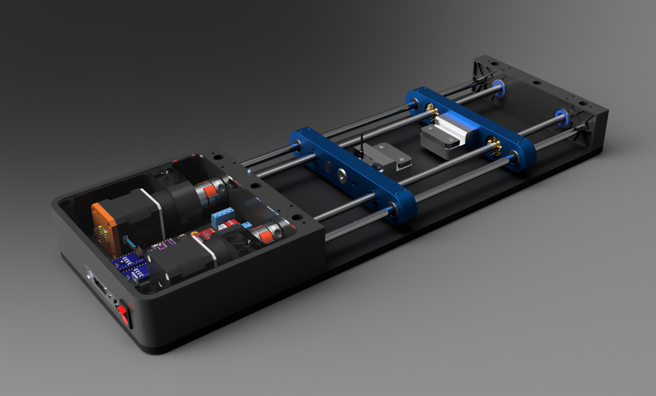
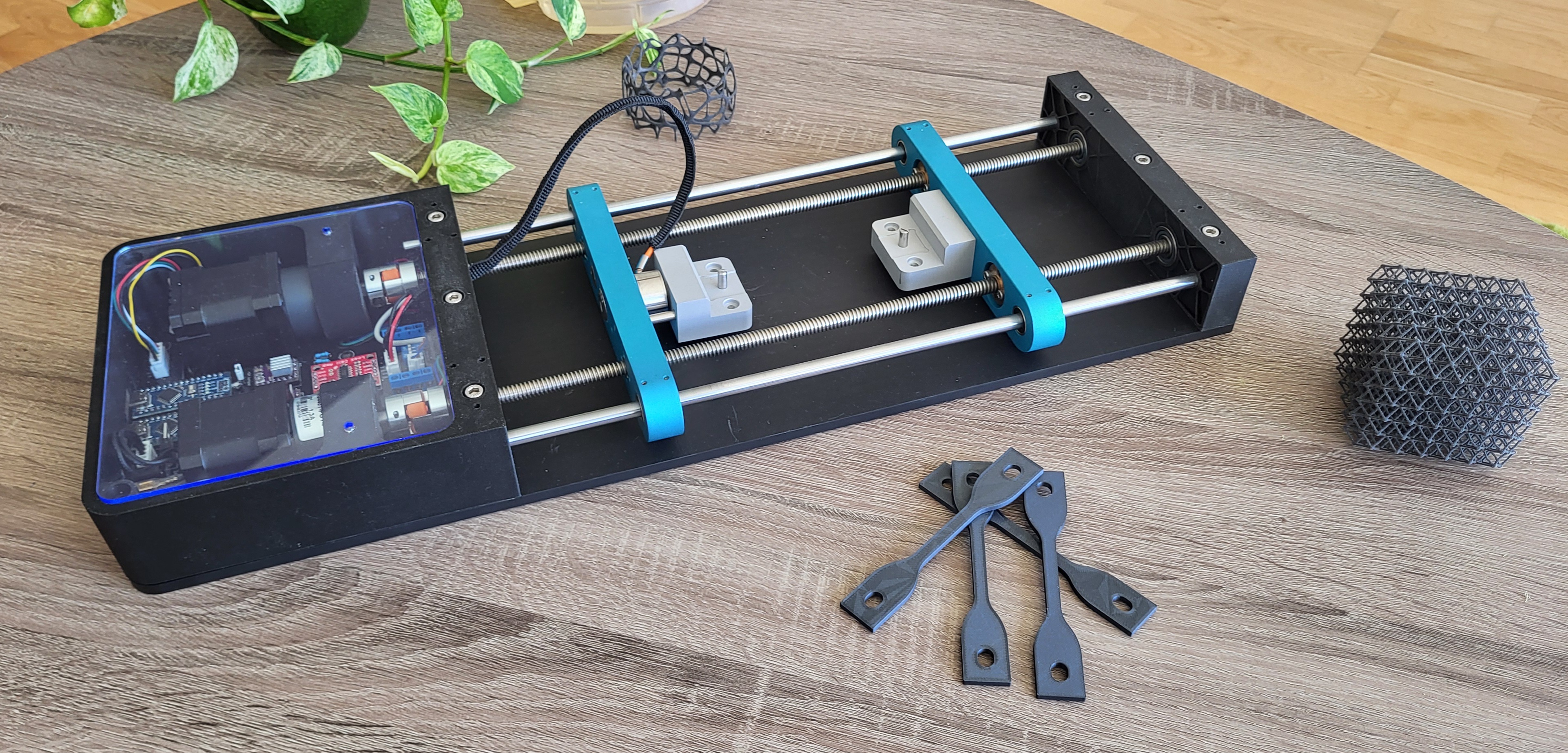 First Stretch 2.0 prototype unit
The core mechanical structure and operating principle remain unchanged with dual-threaded 8mm lead screws & 8mm linear rods similar to Stretch 1.0 with all tensile forces on the specimen resulting in compressive axial forces on the lead screws. Many subtle refinements were made to the system including nesting the linear bearings and lead screw nuts into the crossheads, shrinking the size of the jaws & using alignment dowels to maintain the uniaxial assumption and angular contact bearings over radial bearings.
The baseplate is a single piece of Type II anodized 6061 aluminum which prevents twisting of the structure under high loads. The mounts continue to be 3D printed to allow complex geometries for mounting, hardware, and wire pass-throughs to keep the part count low. In total, there are 40 unique components (including fasteners & electrical components) in the entire design 20 of which are mechanical.
Electrical Improvements
The majority of the R&D effort was spent on the electrical side in creating a customized PCB which allowed us to shrink the volumetric form factor by 1/2 and reduce the wiring complexity enormously saving us lots of labor time on electrical wiring and debugging.
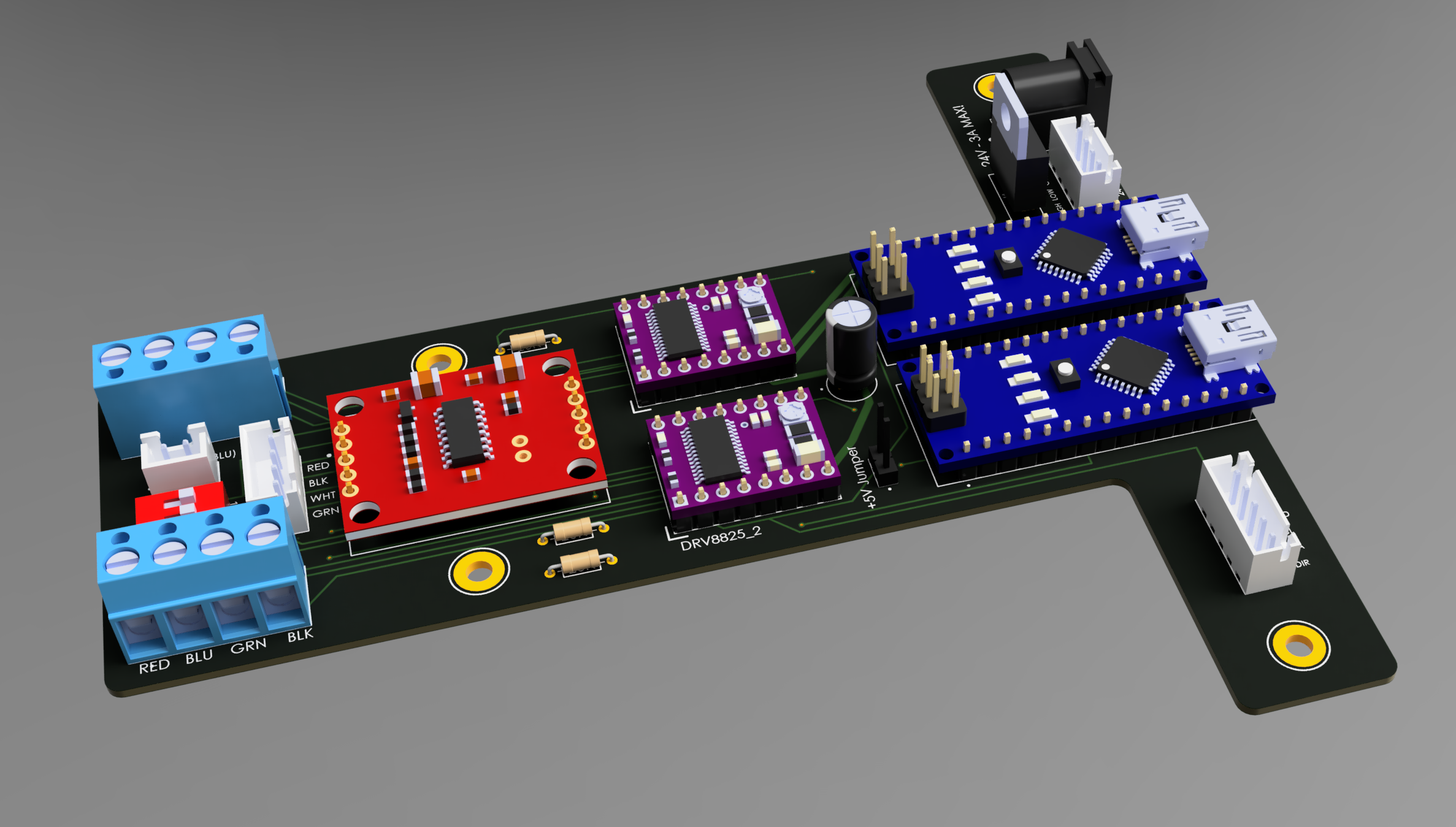 REV2 of the PCB showing all component mounting locations
All components were chosen to be through hole due to the low order quantity size (10 units) and the ease of sourcing components. In the future, I would love to create more PCBs with reflow soldering once I get my hands on the equipment. Positioning of the components was critical in this PCB to align with cable tie-downs in the 3D printed mounts and the USB-C & barrel jack port needed to stick through the mounts to be easily accessible. Fusion360 is awesome for this purpose as you can easily switch from mechanical design to PCB design within the same software and instantly see how the components interact with the mechanical design.
Software Improvements
Previously a button module was used for all jogging control and start/stopping tests and was replaced with a GUI to input parameters, change test parameters, start and stop tests as well as logging data.
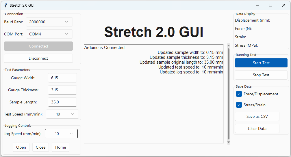 Stretch 2.0 GUI
The GUI was written in Python using the Tkinter & Serial libraries to read data and pass commands over serial communication with the physical unit. All data is saved as a .csv for more detailed analysis later in Excel and is formatted carefully for automatic data analysis with other Python scripts. The GUI can run as a standalone application on Windows or MAC which is convenient for sharing it as it doesn’t require the user to install Python libraries.
A data processing script allows the user to select a folder where a batch of .csv files are stored from various tensile tests and automatically calculates all key values, plots the results, combines all data into a single Excel file and saves images of the results to the same folder.
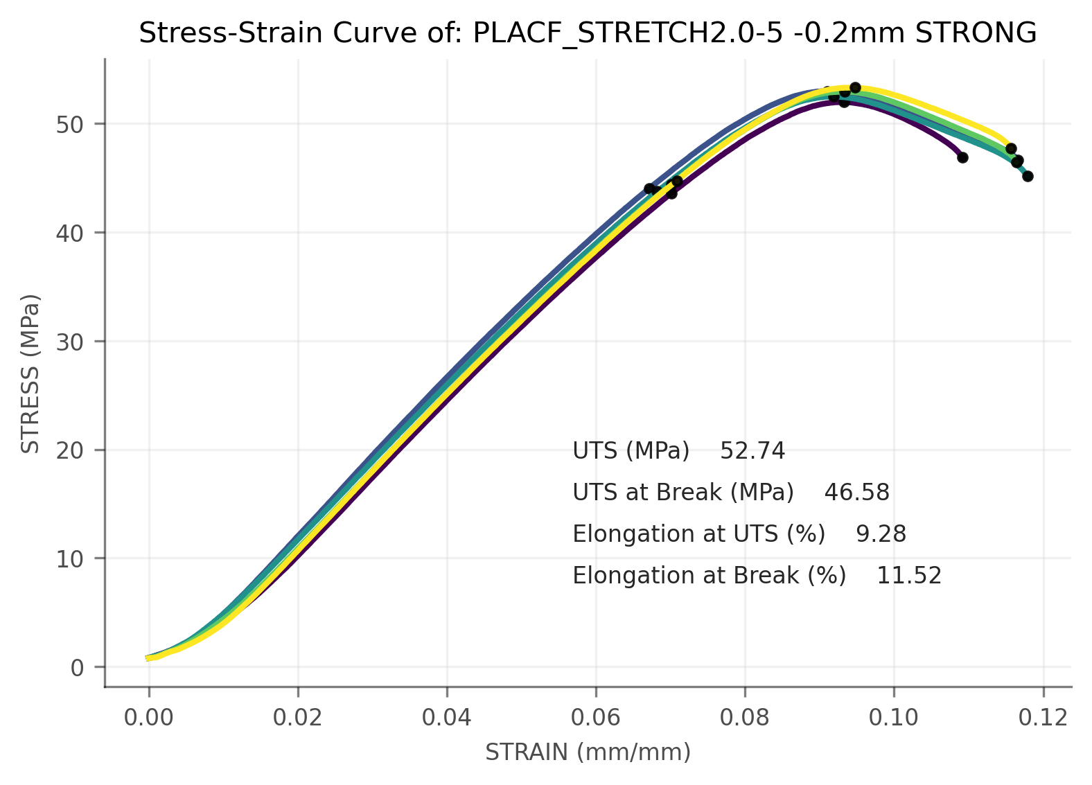 Stretch 2.0 Sample Output
Future Improvements
Stretch 2.0 is much closer to the idealized version of this product in my mind but I want to make a few more changes before releasing it including.
- Local Displacement: Currently the magnetic encoder measures global displacement with a magnet on the leadscrew. For high elongation materials (PET, TPU…etc) this is acceptable but for more brittle materials this doesn’t capture localized displacement dynamics which has a large effect on the accuracy of your results. Currently working on a low-cost extensometer with a linear potentiometer and digital image correlation (DIC) in parallel.
- Live Graphing: Currently not supported in the current architecture due to wanting to drive the cost down on the MCUs by using Arduino Nanos. In the future, if DIC is used a Raspberry Pi may have the computational capacity to support live graphing.