EBike - 3000W
Another COVID-19 Project with maximum fun/$ ratio and heavily inspired by Tom Stanton.
Summary
- COST: ~ $838 CAD
- Financing: Personal :(
- TIME TO COMPLETE: ~ 2 Months (~ 125 working hours)
- Ideation: 5 hours
- Design: 40 hours
- Mechanical Build: 15 hours
- Electrical Build: 5 hours
- Integration Hell: 40 hours
- Testing: 20 hours
Introduction
The original idea of this project was to modify my existing mountain bike to save the costs of having to buy an electric bike. A really important constraint for this project was that I wanted the normal cassette, chain, and shifting to be functional to allow me to switch back to “normal” biking mode with the removal of the timing belt. This was so I was never limited by battery range and could continue pedaling with no additional motor load after the battery had depleted.
Modelling
To help constrain the variables such as motor specifications (kV, Torque, Watts), gear ratio, battery (capacity & Voltage), and more a basic force balance was conducted. The resistive forces considered were:
- Air Resistance: \(F_d = 0.5*A_d*C_d*\rho _{air}*(v+v_w)^2\)
- Air Density ($\rho _{air}$)
- Frontal Area of bike ($A_d = 0.5 m^2$)
- Drag Coefficient ($C_d = 0.63$)
- Velocity of rider and wind (-$v_w$ if headwind)
- Rolling Resistance: \(F_r = C_{rr}*M*g*cos(\alpha)\)
- Rolling Resistance Coefficient ($C_{rr}$)
- Mass of rider & Bike ($M$)
- Alpha ($\alpha$) is the angle of incline
- $\alpha = tan^{-1}({s \over 100})$
- Percent grade of the hill ($s$)
- Gravitational Resistance: \(F_g = M*g*sin(\alpha)\)
- Mass of rider & Bike ($M$)
- Alpha ($\alpha$) is the angle of incline
- On flats this becomes 0
- Mechanical Resistance: \(F_g = M*g*k_b\)
- Mechanical Friction Constant ($k_b$)
- With a well-lubricated system is usually constant around 2% of losses
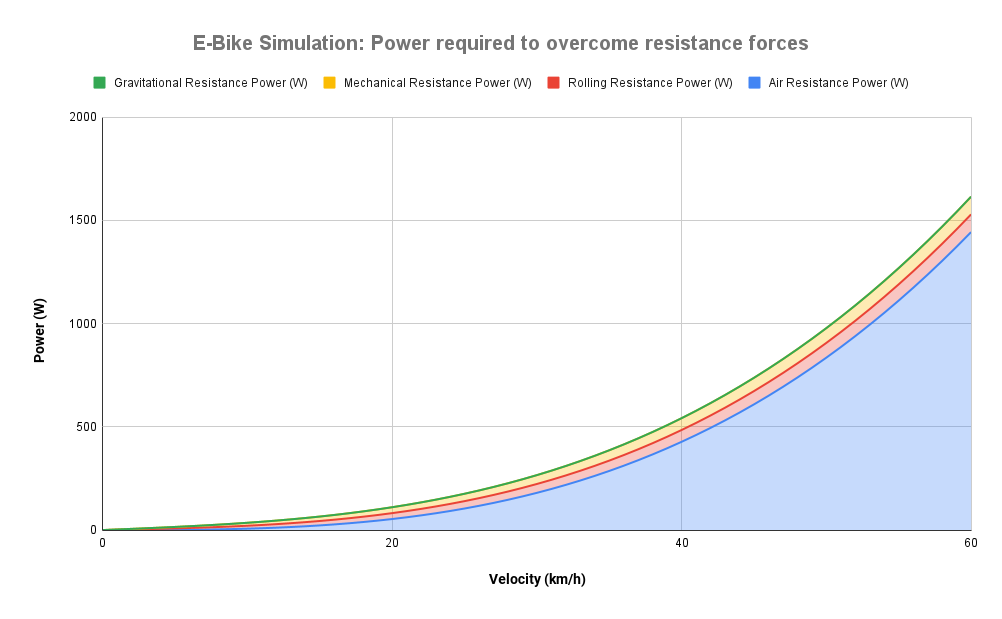 This graphs really illustrates the hard physics reality that $P \propto v^3 $ with aerodynamic drag.
It’s amazing how going from 0 to 1% steepness equates to a jump from 0% to 35% of the power required to maintain that velocity (at 26 km/h).
%20%5BW%5D%20(2).png) Gives us a rough sense with 21700 cells, 12S4P (43.2V Nominal) battery pack our projected range
Gives us a rough sense with 21700 cells, 12S4P (43.2V Nominal) battery pack our projected range
The above graphs were simulated with no head or tail wind, 0% hill steepness, 82kg rider, and a 15kg bike. By doing a sensitivity analysis with all these values I settled on a ~10 Nm motor and 12S4P Li-ion battery pack.
Build
Mechanical
Initially, I attempted to use photogrammetry to scan the bike to save me time having to CAD the complex geometry of the frame. Makes you really appreciate the intricacies of high-volume steel frame bending and welding! Ultimately, photogrammetry never was able to provide satisfactory resolution so I ended up CADing the model by taking many individual measurements at a set spacing from a datum.
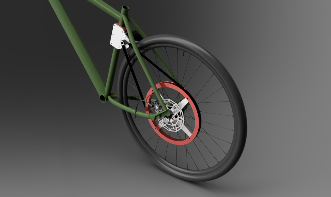
After some back and forth I decided to locate the motor behind the seat post for safety to keep it behind the user instead of between the legs close to the center crank. This limits the rigidity of the motor mounting and I may remake the motor mount in the future to add some needed stiffness.
.jpg)
FEA
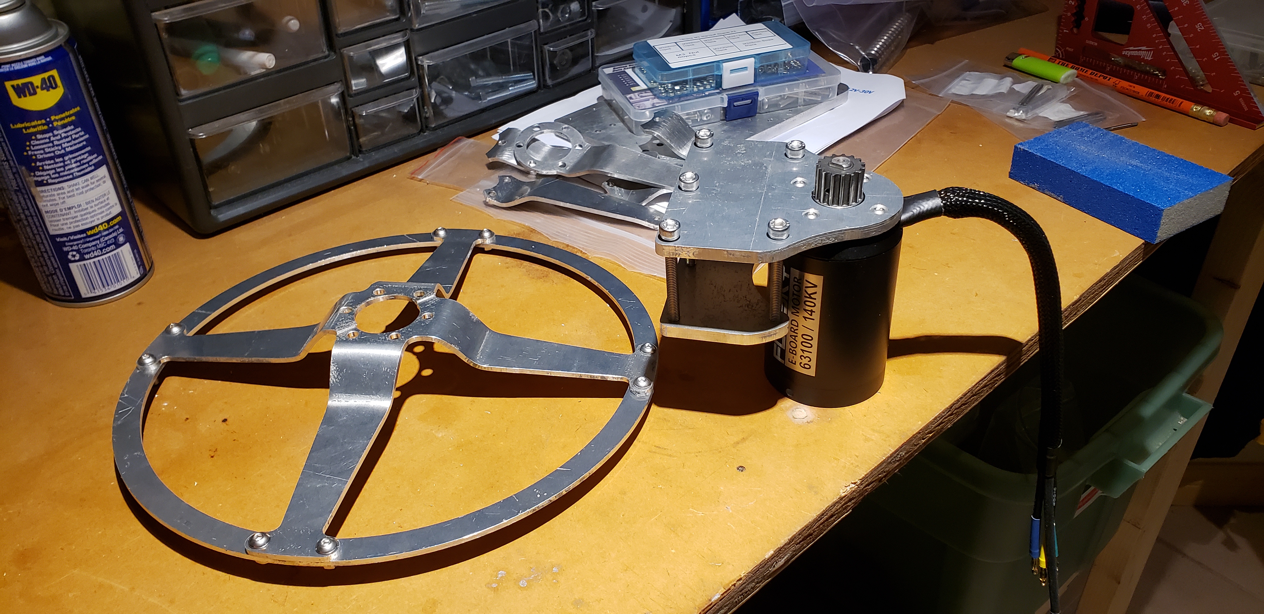
The most complex mechanical component of the build was the rear pulley that had to interface with the wheel, avoid the rear disk brake and take the torque load from the motor. I iterated the design many times including some FEA analysis which showed me I should add an additional retaining ring to connect the four arms to reduce the displacement from ~0.9mm to 0.15mm at full load.
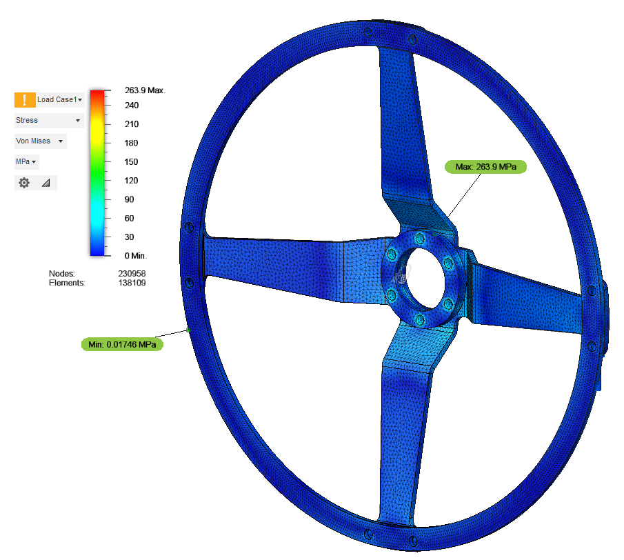
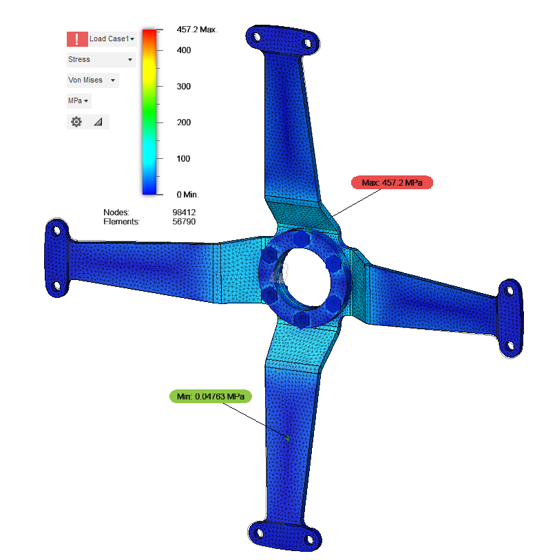
These images show Von Mises (complex loading), exact stress values are inaccurate due to the singularities that occur at the sharp edges of the bolt holes where it shows “max stress”. Used as reference.
Manufacturing
All aluminum parts for this build were machined on my DIY 800W CNC which was really awesome to see it being such a useful tool.
Let me warn you now if you are doing ANY metal bending over 1/16”, get a bending brake. Bending 1/8” aluminum in a benchtop vise with a 2x4” is the most strenuous, inaccurate manufacturing technique I have ever used. You don’t even need a dial indicator to measure the runout - it’s visible to the human eye! Luckily, after much tweaking I was able to greatly improve the runout relative to the wheel axis and remove unwanted vibrations from the ride.
Electrical
Electrical wiring for this project was very simple and mostly plug-and-play. Both the VESC and motor I bought from Flipysky and were both well-built, black aluminum anodized finish and are running strong! I also bought the Bluetooth module that pairs with the VESC so I can watch live telemetry through the phone on my handlebars. Additionally, the fantastic open source software by VESC Project allows you to store all telemetry data as a .csv to analyze later with GPS tags along the route
.gif) VESC Tool Log Analysis showing the speed along the entire journey. Max Speed: 52.6 km/h!
VESC Tool Log Analysis showing the speed along the entire journey. Max Speed: 52.6 km/h!